
Every year, on the Saturday before Thanksgiving, the Western New York Physics Teachers Alliance (WNYPTA) puts on its Physics Olympics for area high school and middle school students. We try to make it a low-key affair (one member calls it "the anti-Science Olympiad").
The Crusher
One of the traditional events at the Physics Olympics is the structure building contest. The actual structure changes from year to year. We have built bridges, cranes, towers, and cantilevers with the usual craft sticks and hot glue or sometimes with straws and toothpicks or other material. What I want to share on this blog post is how we test-to-failure some of these structures. Years ago, we used the usual low-tech methods like hanging a bucket from a bridge and gradual filling it with water. While time-honored, I wanted to add a little razzle-dazzle to the event. So I made the Crusher (seen below with the latest version at the end of this blog).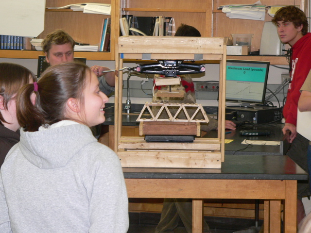
The Crusher is a simple structure; it is just a crate that holds a Vernier Force Plate on the bottom and the loading mechanism above. That mechanism consists of an old scissors car jack with a swiveling plate below (to make sure that the load is applied across the structure even if it is not built perfectly level). With a computer running Vernier's LoggerPro software and projecting to a screen at the front of the room, the entire room can watch the as the load is increased until failure. You can see an example in the background of the above picture. And we can print out the graph for the team to bring back to school for bragging rights. However, there was one detail that took me a while to figure out.
The Razzle-Dazzle
The one detail that I wanted for the display was to have the Maximum Load shown. The problem was that meter-display box would show the current load. Once the structure was compromised, the display would not show the maximum. However, after a couple hours of trying various settings, I figured out what to do. I include the details below for those readers who use Vernier products and who might want to do similar.
First set up two pages in LoggerPro. One page will have the raw data in spreadsheet form. Add a "calculated column" which stores the maximum value of the "Force" column. On the second page, add a graph of the Force and a meter showing the Maximum Force. Here is what took me a few hours to figure out; there is an option under the "Experiment" toolbar called "Live Readouts". When zeroing-out the Force Plate when the structure is placed on it, the "Live Readouts" options has to be enabled, but then it has to be un-enabled when the load is being applied and until after the print-out of the graph has gone through. If you are successful, you will get a page showing something like below.
If you are interested in using this setup in your classroom or extra-curricular activity, I am willing to share the LoggerPro file. Just email me at the blog's associated address.

More Razzle-Dazzle
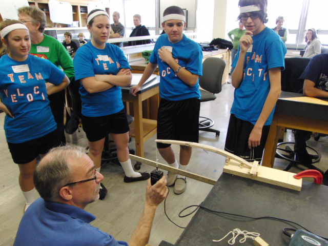
This year, I am going to add a new component. Vernier's DataShare feature (which I have written about before) will allow me to broadcast this graph to those students (and parents) who have smart-phones with a web-browser.Here is an example of the WNYPTA cantilever event from 2011 using the same LoggerPro setup as above but with a Force Sensor instead of the Force Plate. The scoring for this event was based on the product of the lever arm distance and the maximum load. By inserting a Parameter Control, I can input the length of the arm and LoggerPro will calculate the above product and display it for all to see up front.
 l
lThe Crusher, 2nd Modification
You might have noticed a major problem with the version of the Crusher shown above; it applies the load to the top of the bridge. One of my projects this summer was to modify the Crusher to apply the load to the deck of the bridge so that I can use it in the Intro to Engineering course I am teaching this year. You can see that major modification below. In essence. I just added a removable rod that can go through the bridge and apply the load inside.

Here are some hints if you want to build one of your own.
Bill of Materials
Scissors Jack
you can borrow the one from your car or find one at a junk yard for $5-10
Top and bottom plates
I modified an old teacher cart in the example above, and have used old pressboard from an Ikea desk for another, but you can make yours with some scrap plywood and scrap 2x4 lumber screwed in at the corners to attach the pillars.
Pillars
hockey sticks are used here simply because I had a number of them available, but you can use 1x3 or 2x2 lumber available at your local hardware store. If you have four 2-3 foot long 2x4’s lying around, you could use those also but the structure will be heavier. Start with 3 foot lengths since you can raise the Force Plate with books if needed. You can trim them later when you have a better idea about what height you need.
Load Frame
the lumber you use for three parts of the frame (the horizontal member attached to the scissors jack and the two vertical members) can be the same that you use for the pillars, however, the lumber you use for the load member you need to choose with care. It, along with the Load Foot (see below), need to be small enough to pass through the bridges you are having your students build. For the bridge I show in the photo, the pass-through is about 2 inches square. I hold the lower member to the load frame with steel and magnets to facilitate easy disassembly, but you could attach with a couple of rubber bands.
Load Foot
If you want to exert the downward force on only a small portion of the structure, you will need to affix a load foot to the lower load frame member. I have used the swivel head of an old C-clamp to allow the load foot to compensate for less than level bridge decks. The car was added just for whimsey.
Structure Supports
If you want to specify a bridge-span wider than the Force Plate, you will need to tack together a simple frame. Easy enough to do with any scrap you have around.


This is really great. The structure, the razzle-dazzle, and you being generous with us on how to pull it off. Thanks!
ReplyDeleteI wonder if you ever explore the dynamics just before (and maybe just after) the failure. The example you showed was interesting because it shot up right before failure. Was that a change in the rate of increasing the load or a shift of the structure (or something else)?
This Physic Olympics event is only an hour in length, for both build and testing, so we don't get too technical. When I get an Intro to Engineering course going at my school, I will do some more in depth analysis of structures.
ReplyDeleteAnd about the graph shown. I needed a printout for our school's Open House, so I just pressed down on the plate to get a gradually increasing graph. I guess that I put an extra push at the end. However, the graph in the background of the second picture is for an actual structure.
ReplyDelete